Getting Started

General Information

This page is definitely under construction as I am not exactly sure if and when I will be able to lay out detailed steps in building this system. I've listed the resources adequately on these pages for anyone with specific knowledge and skill to be able to figure out the steps necessary to complete this project. The process is not for the faint in heart but rather for those who have general knowledge of building kits, PCB boards, soldering, ordering the necessary components and have general knowledge of electronics as well as the Arduino ecosystem of microcontrollers. Please visit and explore the resources at http://skaarhoj.com/ as it is the basis for this whole project.
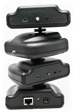
Let us fabricate these devices for you

Building your own solution might not be a feasible idea as this process takes a few hours and maybe days to understand. For this reason we offer our services in constructing these kits and programming the microcontrollers.

Our Services

Schematics and Code

  • Schematics for the Transmitter and Receiver were made in Eagle and are available for download. Feel free to modify these designs as you see fit while conforming to the Open Source licenses describes in the Terms and Condition sections on the About page.
  • The Arduino sketches are available on GitHub.

Upgrade Transmitter to work with ATEM Switchers Firmware 6.0.x

  1. 1. You will need to purchase the FTDI interface for USB. Here is an example from SparkFun: https://www.sparkfun.com/products/9716
  2. 2. Install the Arduino IDE: http://arduino.cc/en/main/software
  3. 3. Download and Copy/Paste all the libraries in the TallyLight_4.2_Update.zip file to the libraries folder of your Arduino IDE installation. Note that the 4.2 Update is compatible with the latest 6.0 Firmware.
  4. 4. Open the ATEM_Tally_Transmitter_433MHz.ino sketch found in the same .zip file.
  5. 5. Set your IDE to USB device as UNO. (Make sure you have the correct USB port selected otherwise its just going to fail)
  6. 6. Open the Tally Light Transmitter and connect the FTDI interface to the FTDI pins (you may need to find a simple 6-pin right-angle header somewhere or just improvise)
  7. 7. Upload the sketch. If all is a success it should say "Complete".